Arduino in detail
What is open source Hardware ?
The Arduino is defined on its website as an open source electron-ics prototyping platform. within the open source hardware movement, technologists share their hardware and software to foster devel-opment of latest projects and concepts .
Source designs are shared during a format which will be modified, and whenever possible, readily available materials and open source tools are wont to create the designs.
By encouraging the sharing of resources, the open source hard-ware movement facilitates development of latest products and styles .
Open source projects emphasize the importance of doc-umentation and sharing, making the community of users an excellent resource for learners.
Arduino in detail
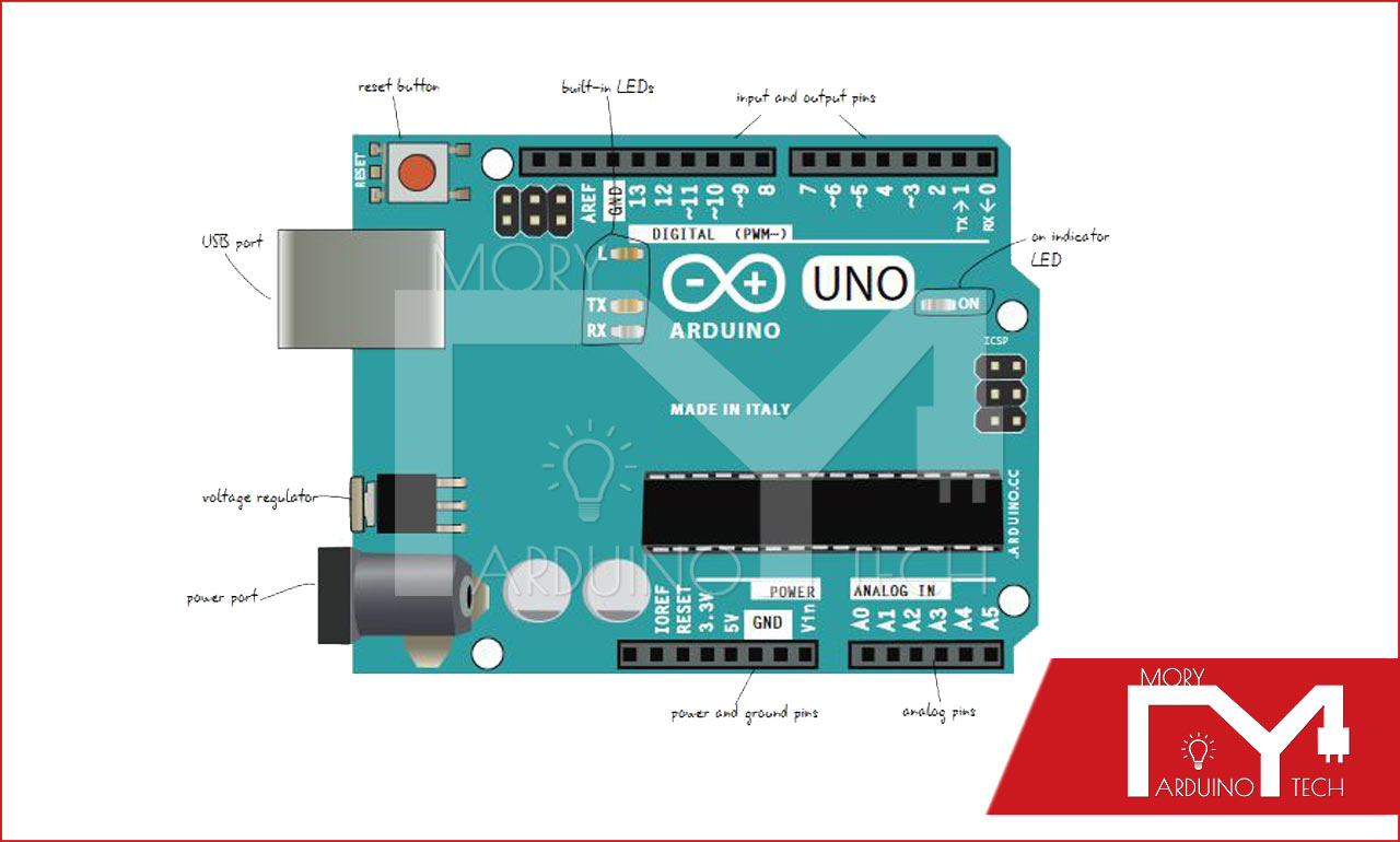
Let’s learn a touch more about what’s on the Arduino board. Remem-ber that there are different sorts of boards, so yours may look slightly different. These figures are supported Arduino Uno revision 3.
We’ll look first at the left side of the board, with the push button , USB port, voltage regulator, and power port.
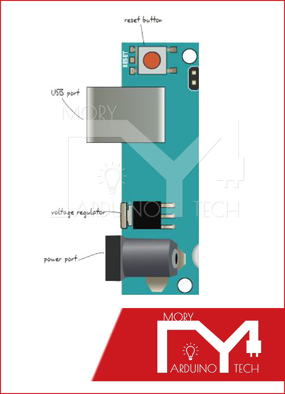
Reset Button
Much like turning your computer off and on again, some problems with the Arduino are often solved by pushing the push button .
The reset button may be in a different location on your board, but it is the only button.
USB Port
The USB port takes a typical A-to-B USB cable, often seen on printers or other computer peripherals. The USB port serves two purposes: First, it is the cable connection to a computer that allows you to program the board. Second, the USB cord will provide power for the Arduino if you’re not using the power port.
Voltage Regulator
The voltage regulator converts power plugged into the power port into the 5 volts and 1 amp standard used by the Arduino.
Be careful ! This component gets very hot.
Power Port
The power port includes a barrel-style connector that connects to power straight from a wall source (often called a wall-wart) or from a battery.
This power is used instead of the USB cable.
The Arduino can take a wide range of voltages (5V–0V DC) but will be damaged if power higher than that is connected.We’ll take a closer look at the other side of the board now (Fig-ure 2.3), which includes the digital, analog, and power pins as well as the actual chip for the board.
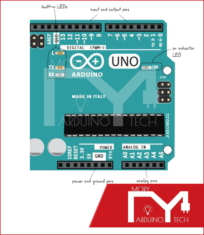
Built-In LEDs
The LEDS marked TX and RX show whether your Arduino is sending or receiving data. The one marked L is connected to Pin 13.
ON Indicator LED
This LED indicates that the Arduino is getting power when you turn it on.
Digital I/O Pins
The holes on this side of the board are called the digital input/out-put pins.
They are used to either sense the outside world (input) or control lights, sounds, or motors (output).
TX/RX Pins
Pin 0 and Pin 1 are special pins labeled PIN RX and TX. we’ll cover this in additional detail later, but it’s good practice to go away these pins empty. Any changes you create to your program won’t load if something is plugged into Pin 0.
ATmega328P, Black Chip
The black contribute the center of the board is an ATmega328P. this is often the “brains” of the Arduino : it interprets both the inputs/outputs and therefore the programming code uploaded onto your Arduino. the opposite components on the board enable you to speak with this chip when creating projects.
Power and Ground Pins
Pins associated with power are located here. you’ll use these pins to run power from your Arduino to your breadboard circuit.
Analog Pins These pins take sensor readings during a range of values (analog), instead of just sending whether something is simply on or off (digital).